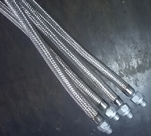
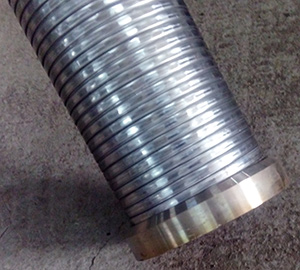
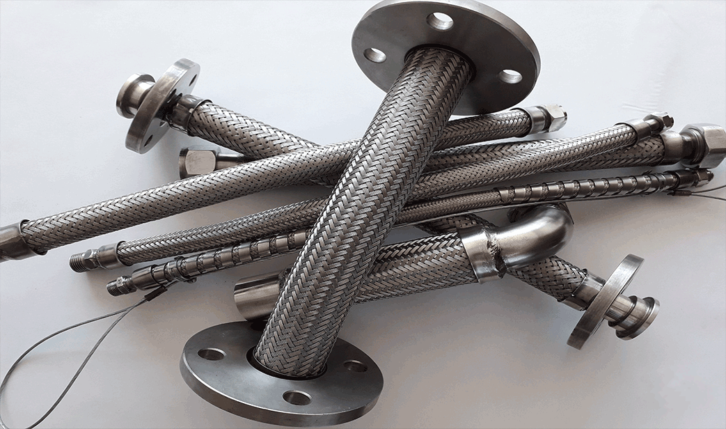
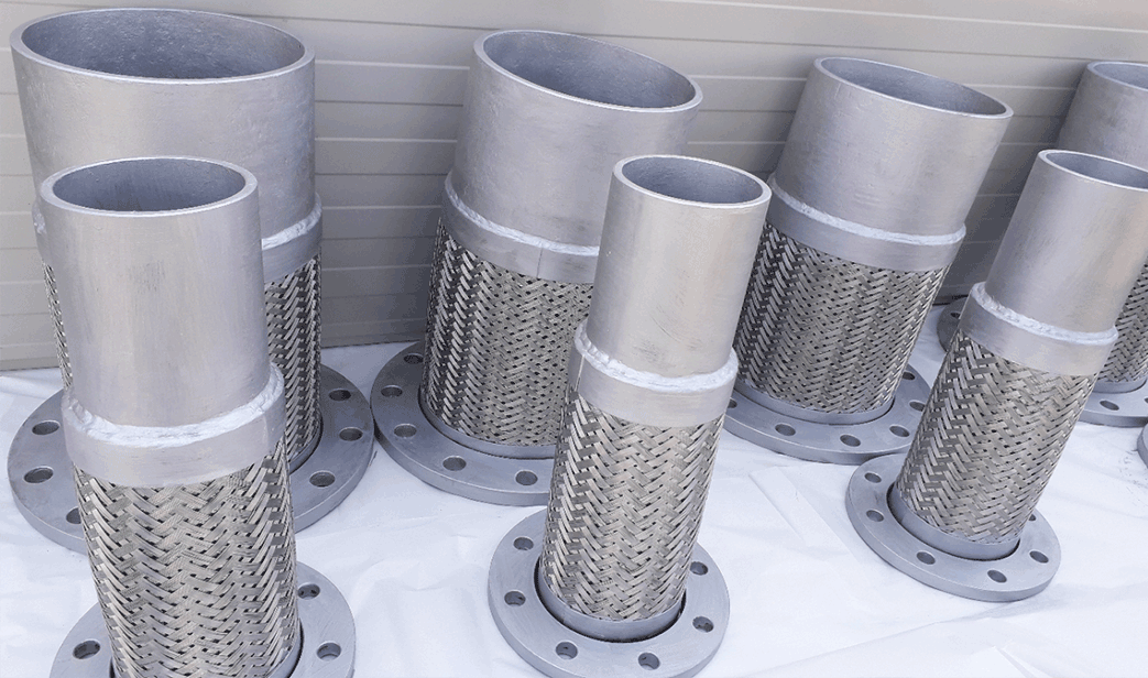
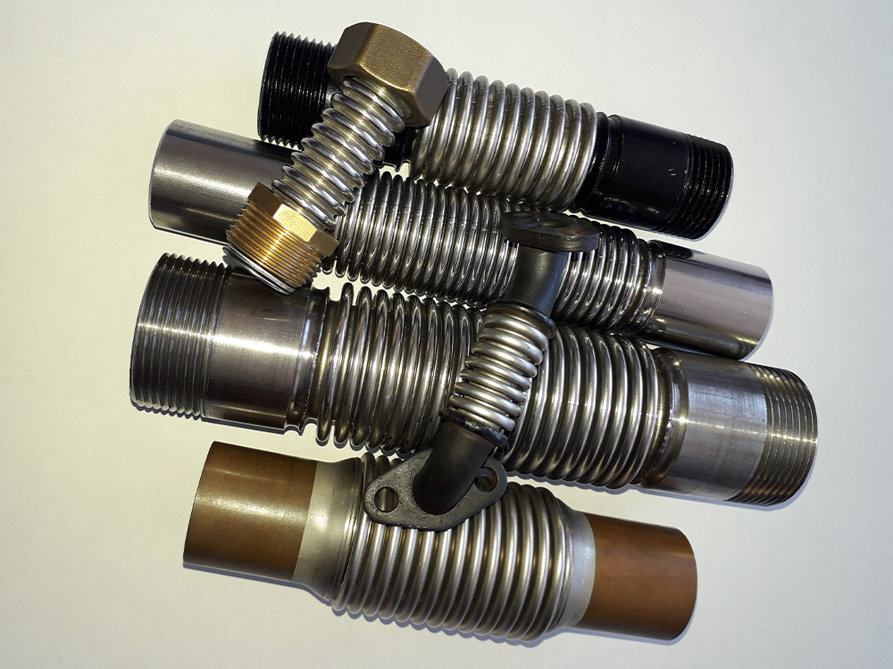
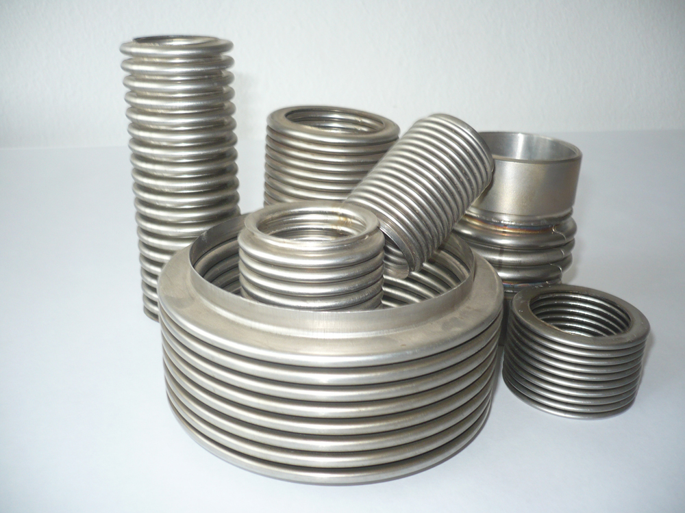
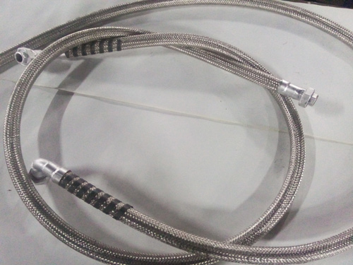
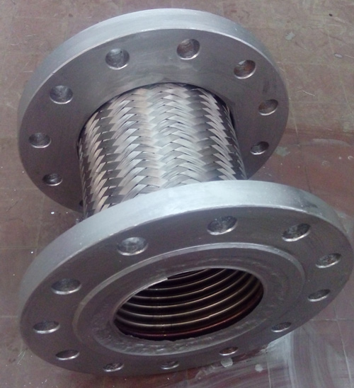
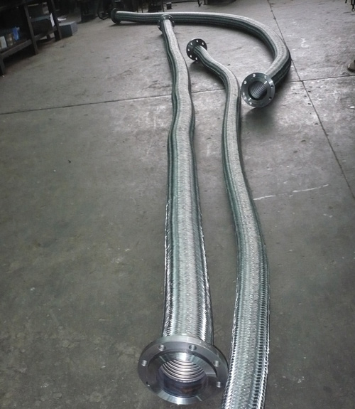
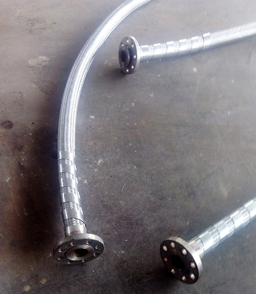
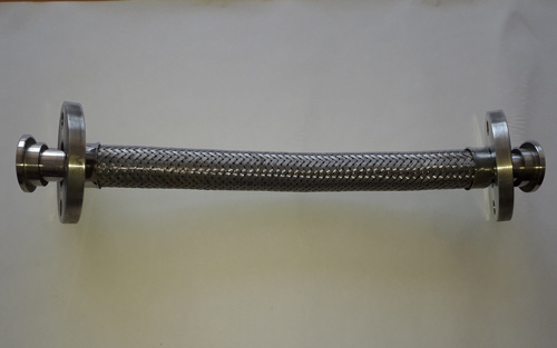
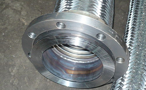
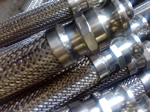
Metal flexible corrugated hoses
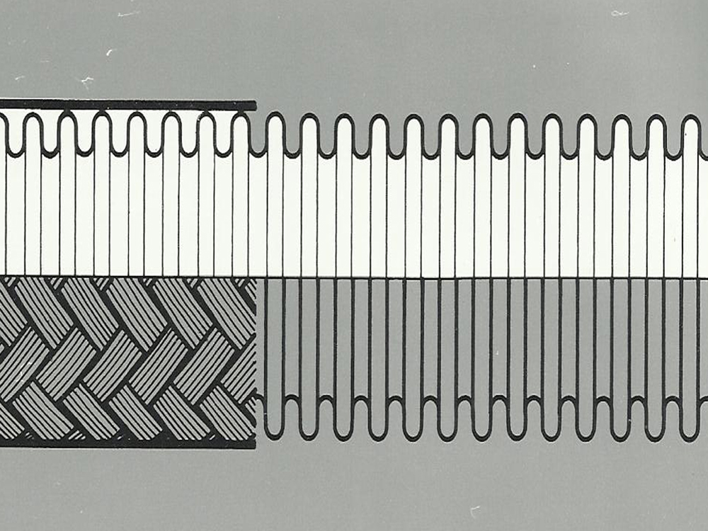
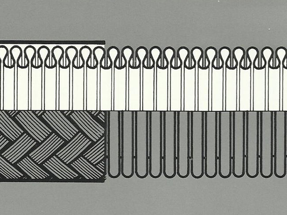
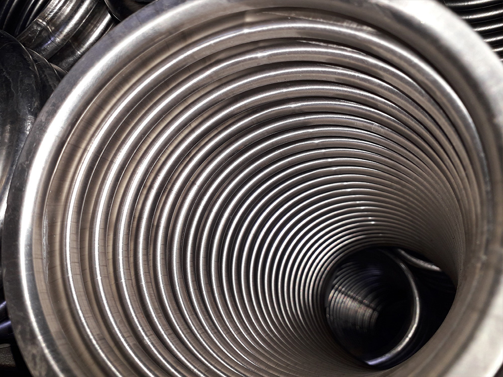
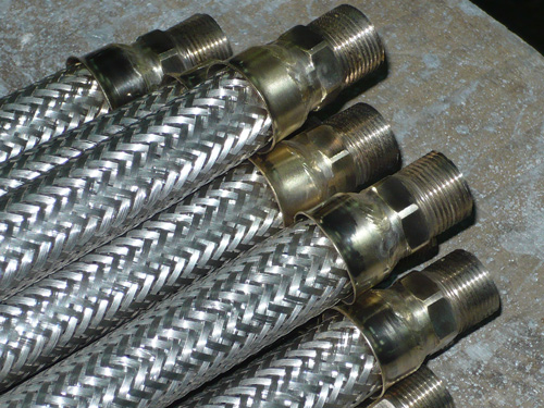
Metal flexible corrugated leak proof hoses have been producing by special hydraulic forming from thin-walled butt welded tubes.The corrugation of these hoses can be helical or annular.
Our hoses MAFLEX N and MAFLEX S have corrugations perpendicular to the axis of the hose.
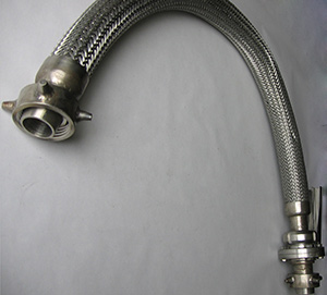
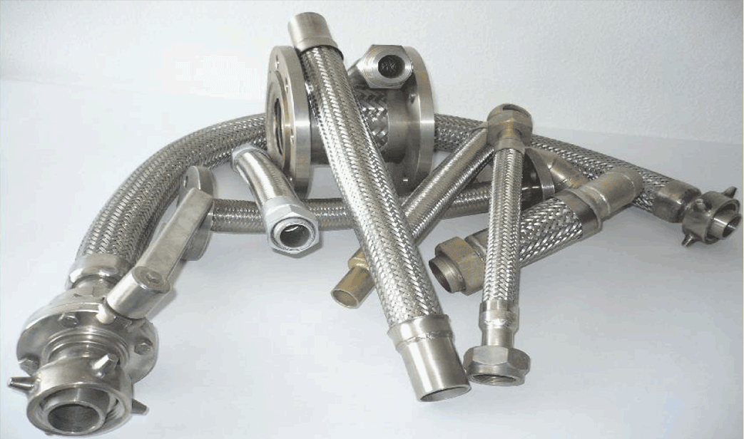
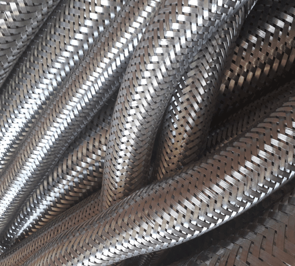
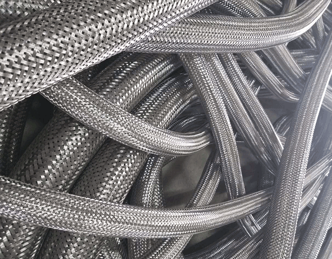
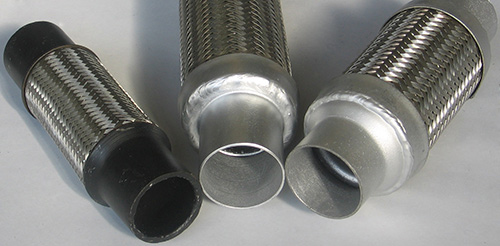
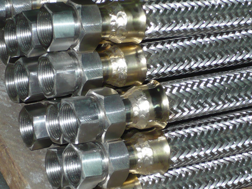
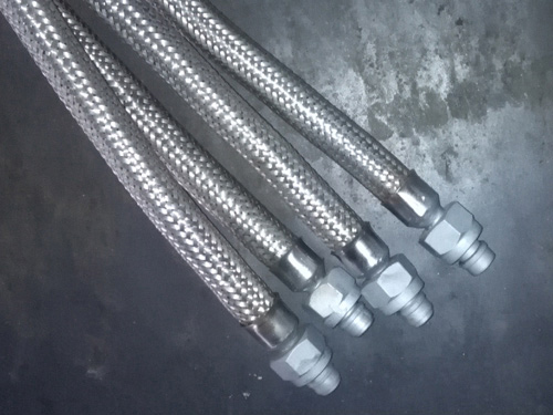
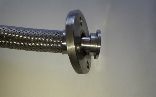
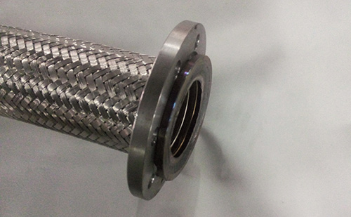
Owing to their corrugated form, metal flexible hoses have high resistance to pressure acting to radial direction and less one to hose axis. To increase pressure resistance, these hoses are single or multiple wire braided.
Number of braids, braiding material and hose characteristic, depending on number of braids, are indicated for each type of hoses on the next pages.
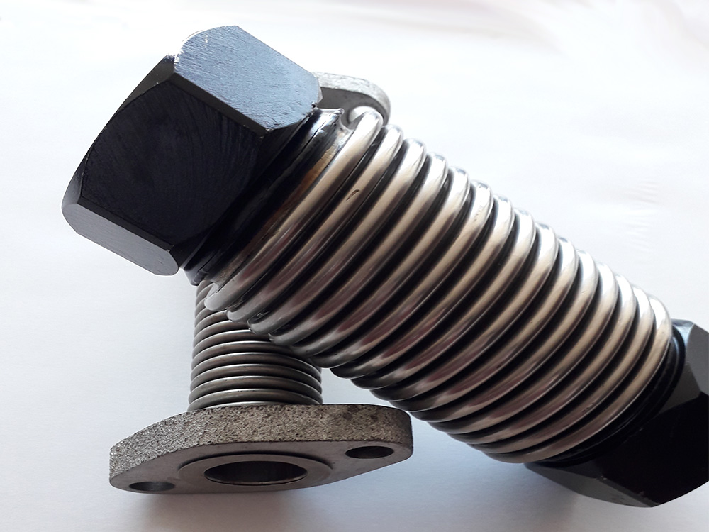
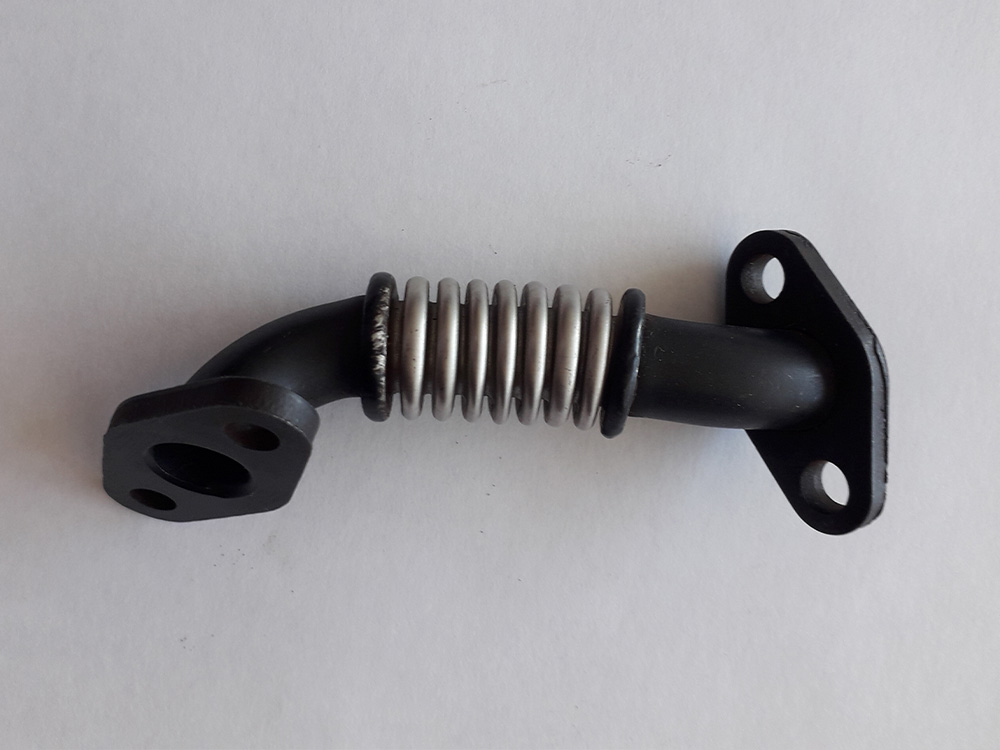
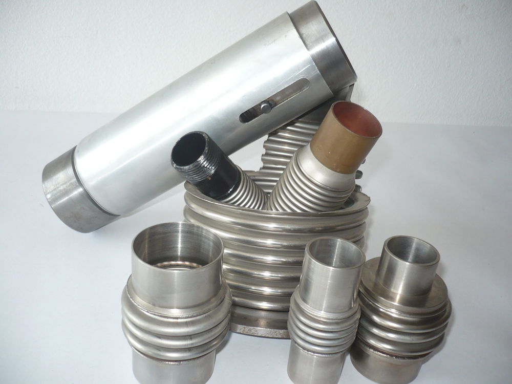
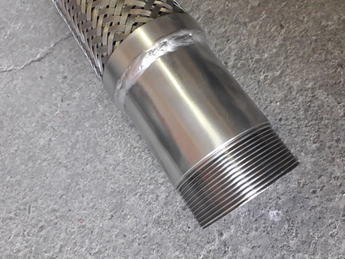
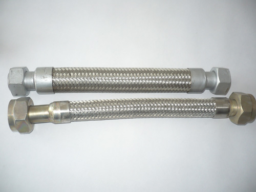
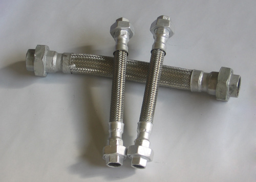
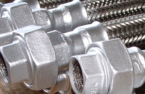
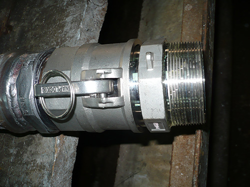
Metal flexible corrugated hoses can be fitted by flanges, threaded connectors, tube weld ends etc. The assembling connectors with the hoses is carried out by protective gas welding, brazing, silver soldering and mechanical jointing.
Materials:
As flexible conduits they often have to operate elastically under extreme conditions and, because of the thin walls as compared with rigid piping, they must be especially corrosion resistant.
Moreover, these hoses have to meet the following requirements:
- good cold forming properties,
- good strenght properties,
- optimal thermal stability,
- good corrosion resistance,
- high reliability in operation.
Materials:
Austenitic stainless steel according to material no.
- W.Nr. 1.4571 ( AiSi 316 Ti),
- W. Nr. 1.4401 ( AiSi 316),
- W. Nr. 1.4404 ( AiSi 316L),
- W. Nr. 1.4541 ( AiSi 321).
Description:
- absorption of movements (movements of one or both end fittings with large amplitude and low movement frequency),
- absorption of vibration (movement with low amplitude and high frequency),
- absorption of thermal expansion of hose assembly,
- compensation of parallel offset in pipelines,
- absorption of angular movements.
Definitions and explanations of hose characteristics
Nominal size (DN)
according to ISO 6708 is represented by numerical indication of size which is common for all components in piping system. Nominal diameter is a convenient rounded off number reference applications and it hasn't to be equal to the actual inside diameter of hose.
Inside diameter (d 1)
is an effective section of hose and mostly equal to its nominal size.
Outside diameter
tDiameter of cylinder enveloping the straightened out tube.
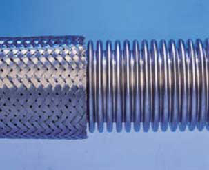
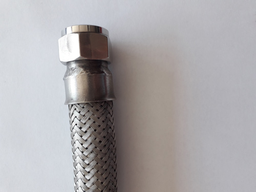
Braiding
With the aim of improving the pressure resistance and mechanical protecting, hoses can be covered by single or double braiding. The hoses for vacuum applications are not normally braided.
Working pressure ( Pr)
is the maximum pressure which a hose can withstand during the operation at room temperature (20ºC) and at fluid without pressure fluctuations and vibrations. The working pressure is established as a quarter of the bursting pressure:
Pr= bursting pressure/4
If the hoses are exposed to thermal stresses that, is to temperature higher than room one, the working pressure will be decrease. It is established by the following formula:
Pdop=Pr x Kt
Minimal bending radius
is a minimal of axis turn of hose permissible in operation . It is determined on the base of measurement and calculating and given in the tables as static for one bending only and dynamic for repeated bending in operation.
The bending radius un active position shall be larger than or equal to the minimal bending radius given in the tables.
The bending radius essentially influences on lifetime of hose. Its increasing will augment lifetime of hose.
Hose mass
given in the tables, is determined by calculation and measurement. The permissible deviation must be kept in limits ± 10%.
Maximal permissible working temperature
is lowest maximal permissible working temperature of any constituent component:
- hose material,
- attachment method of connecting elements and hoses
- attachment method of connecting elements and hoses
- connection method etc.
The working temperatures of hoses without connecting elements are given in the description of the individual hose type.
Quality control and certificates:
The quality control is a matter of exceptional importance in consideration of specific quality of flexible hoses as in view of their production so with regard to their exploitation.Material control
The high quality material is one of the most important factors in high quality flexible corrugated hoses manufacturing. Therefore, we have been purchasing materials from reputable European manufacturers. All materials have to be followed by corresponding certificate such as the one according to EN10204-3.1. Besides, all purchased materials are submitted to the testing of chemical, mechanical characteristics , resistance on inter crystalline corrosion etc.
Manufacturing process control
The particular care must be taken of the dimension accuracy control and careful material working out. The basic material of hose is exposed to considerable strains during the hydraulic process and it is simultaneously very reliable way of material testing.
Leakproofness of hoses
To check up the leakproofness of hoses, pneumatic or vacuum tests can be done. The pneumatic test is carried out by air or nitrogen under water. The nitrogen testing is more expensive and it has to be carried out in those hoses which are mainly used in conveying the gaseous or very liquid media During this test hoses are exposed to a pressure equal 10 % of working one or 2 bar minimum. The vacuum test is applied only in special cases it is considerabley expensive and therefore,it must be apart agreed.
Testing by hydraulic pressure
This testing is carried out in the aim of checking up the hose solidity by hydraulic or pneumatic testing pressure. A straight sample of hose at room temperature shall be subjected to a testing pressure which shall be 1,5 times the maximal permissible working pressure. Unless otherwise stated, the test medium shall be water. The test pressure shall be applied and maintained for a sufficient length of time to permit a visual examination of all surface joints. The testing by pneumatic test pressure is carried out under same conditions as hydraulic testing but the medium is gas. Pneumatic testing is potentially a much more dangerous operation than hydraulic testing in that , irrespective of size, any failure during test is likely to be of a highly explosive nature. Therefore, this testing is applied only exceptional cases by particular agreement.
Certificates
Depending on client's request we or specialized agencies carry out the reception control. Therefore, on the basis of carried out testing according to the reception control the corresponding certificates have to be issued. These certificat is issued in accordance with relevant standard EN10204. If the client doesn't denote, we usually issue the certificate in accordance with EN10204-3.1 .
Installation :
Our hoses are very specific products. They are reliable in operation but they can only function satisfactorily under the condition they are chosen and installed correctly.Correct handling
Since the hoses are manufactured of relatively thin-wall material, it is necessary to treat them carefully so that they would not be damaged before installing. The hoses must be stored straightened out or coiled with a bending radius larger than minimum permissible one. At transport they should not be dragged along the floor or across sharp edges.
Correct choice of a tube length
The correct choice of hose length is very important . Excessive shortness of hose doesn't give the needed flexibility , in that case it is too rigid. In addition, the hose can be damaged relatively quickly close to the end fittings. Excessive long hose is not only too expensive but it is also quickly damaged in operation. In determining the hose length you should use recommendations, and if you are not sure, consult us.
Permissible bending radius must be observed
Non-observance gives rise to damage of hoses. The instructions , relating to pressures, temperatures etc. must be also followed.
No torsion stress
Our flexible hoses can be only subjected to bandings. Torsion stresses must, therefore , be avoided. This can, in most cases, be realized by suitable installing of the hose. In the case of movements in operation, the hose must be installed in that way that the hoses axis and the direction of movement are in the same plane.
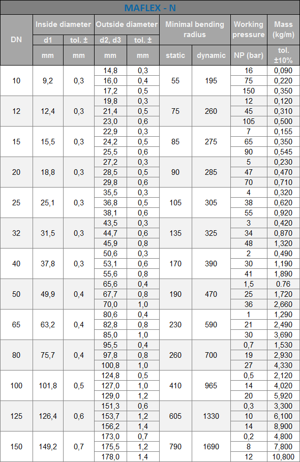
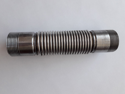
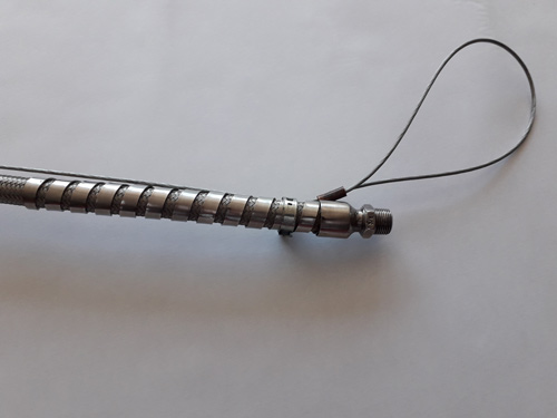
MAFLEX - N
Construction:All metal single-walled flexible hose hydraulically formed from a butt welded tube.
Profile:
Normal parallel corrugations.
Materials:
Austenitic stainless steel according to material no.
- W.Nr. 1.4571 ( AiSi 316 Ti),
- W. Nr. 1.4401 ( AiSi 316),
- W. Nr. 1.4404 ( AiSi 316L),
- W. Nr. 1.4541 ( AiSi 321).
Stainless steel wire according to material no.
- W.Ne. 1.4301 ( AiSi 304).
Flanges, thread connectors, weld ends.
Dimension:
DN 10 to DN 150.
Pressure range:
105 bar max.
Depending on nominal diameter, number of braids, temperature range etc.
Temperature range:
- 196 º C to 600 º C
Application:
The conveyance of fluids and gas under pressure and vacuum. Owing to its all stainless steel construction, it is used in the most applications of corrosive fluids and atmosphere, as compensating elements for absorption, displacement of rigid termical dilatations, compensation of misalignment of rigid tubes and the like.
Maximal permissible working pressure at temperatures higher then room one can be calculated as follows: Prt=Pr x kt (bar)
| WORKING TEMPERATURE t(C) |
20 | 100 | 150 | 200 | 250 | 300 | 350 | 400 | 450 | 500 | 550 | 600 |
|---|---|---|---|---|---|---|---|---|---|---|---|---|
| REDUCTION COEFFICIENT kt(-) | 1 | 0.95 | 0.88 | 0.83 | 0.79 | 0.75 | 0.72 | 0.68 | 0.64 | 0.61 | 0.59 | 0.57 |
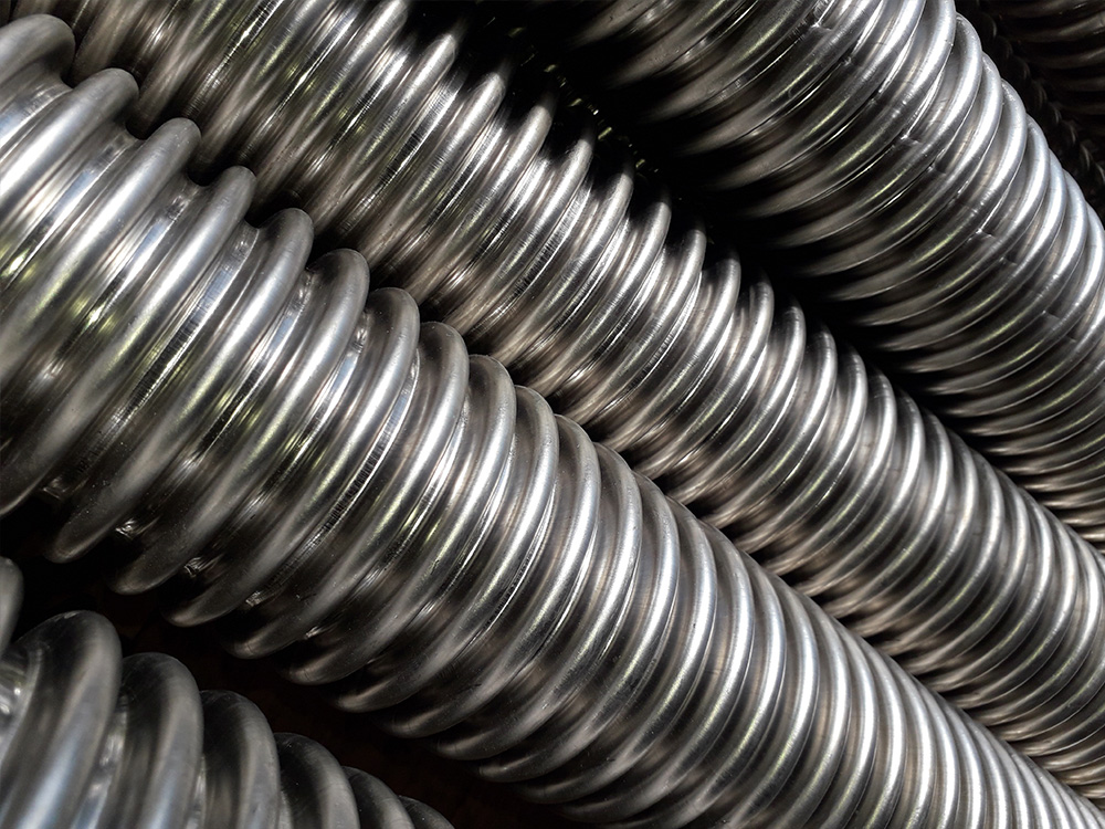
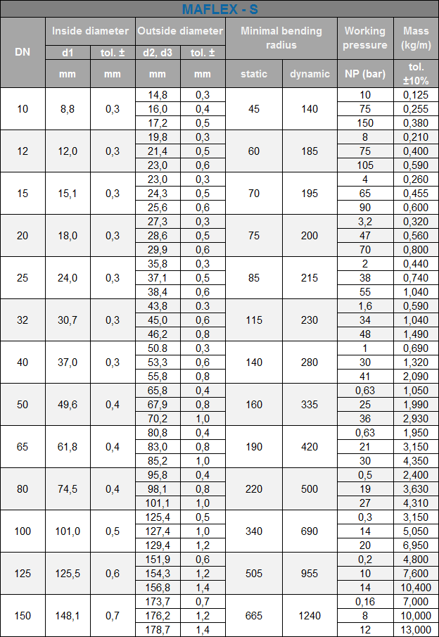
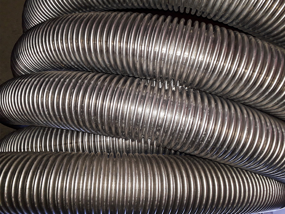
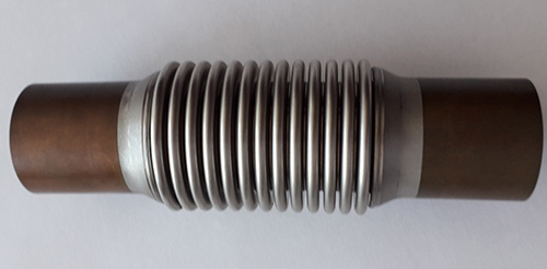
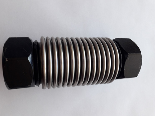
MAFLEX - S
Construction:All metal single-walled flexible hose hydraulically formed from a butt welded tube.
Profile:
Close pitch parallel corrugations (omega profile).
Materials:
Austenitic stainless steel according to material no.
- W.Nr. 1.4571 ( AiSi 316 Ti),
- W. Nr. 1.4401 ( AiSi 316),
- W. Nr. 1.4404 ( AiSi 316L),
- W. Nr. 1.4541 ( AiSi 321).
Stainless steel wire according to material no.
- W.Ne. 1.4301 ( AiSi 304).
Flanges, thread connectors, weld ends.
Dimension:
DN 10 to DN 150.
Pressure range: :
105 bar max.
Depending on nominal diameter, number of braids, temperature range etc.
Temperature range:
- 196 º C to 600 º C
Application:
The conveyance of fluids and gas under pressure and vacuum. Owing to its all stainless steel construction, it is used in the most applications of corrosive fluids and atmosphere, as compensating elements for absorption, deplacement of rigid termical dilatations, compensation of misalignment of rigid tubes and the like.
Working pressure (Pr), given in the table, is the maximal permissible working pressure at room temperature. Maximal permissible working pressure at temperatures higher then room one can be calculated as follows:
Prt=Pr x kt (bar)
| WORKING TEMPERATURE t(C) |
20 | 100 | 150 | 200 | 250 | 300 | 350 | 400 | 450 | 500 | 550 | 600 |
|---|---|---|---|---|---|---|---|---|---|---|---|---|
| REDUCTION COEFFICIENT kt(-) | 1 | 0.95 | 0.88 | 0.83 | 0.79 | 0.75 | 0.72 | 0.68 | 0.64 | 0.61 | 0.59 | 0.57 |
BRAIDS
Construction:Round section braiding can be done with sharp obtuse angle
Material :
- Stainless steel wire x 5 Cr Ni 189 according to DIN 17440,material no.1.4301 (AISI 304).
- Bright bronze wire
- Galvanized steel wire
- Other materials such as copper etc.
Inside diameter of braid from 4 to 174 mm
Application:
Braiding the metal rubber and plastic flexible hoses because of mechanical protection and increasing the resistance on inside pressure.
Wire braiding hoses for interference suppression and shielding of cables.
Braids without core for special purposes etc.
| TYPE | MATERIAL |
WORKING TEMPERATURE |
|---|---|---|
| 11 | Galvanized steel wire |
250º C |
| 12 | Stainless steel wire | 400º C |
| 33 | Bright bronze wire | 250º C |

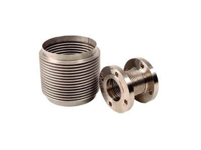
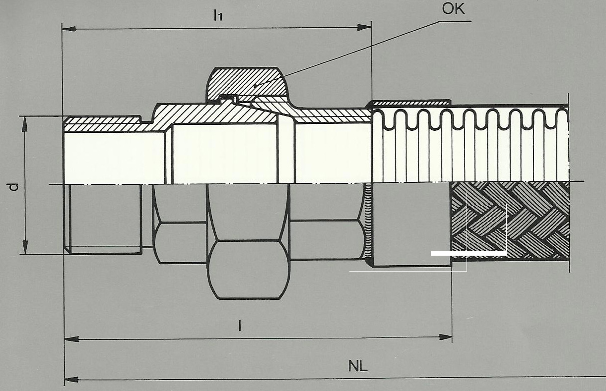
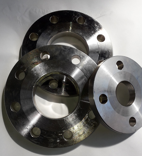
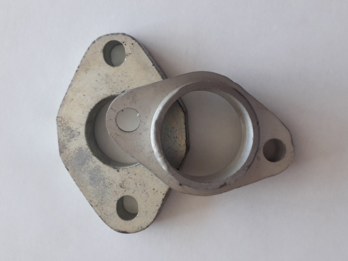
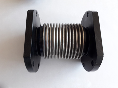
COMPENSATORS
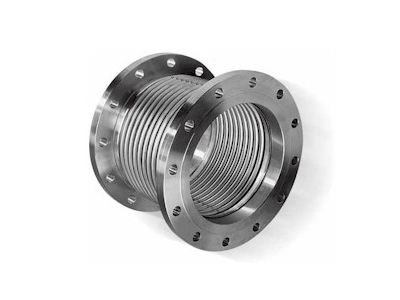
FITINGS
For connecting the flexible hose type: MAFLEX-N and MAFLEX-S
Assembling method – Welded
Assembling method – Welded
| TYPE FITTINGS |
CONNECTION MATERIAL |
MAX.PERM.OPERATING TEMPERATURE |
|---|---|---|
| NC 12 M | Steel | 400° C |
| NC 22 M | Stainless steel | 600° C |
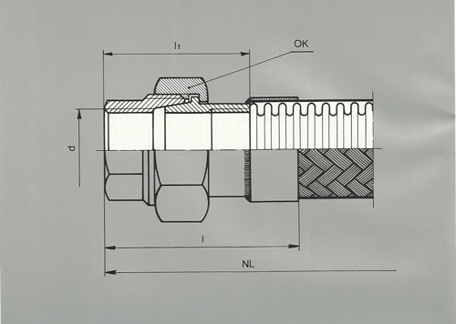
| NP (bar) | 160 | 100 | 40 | ||||||||||
|---|---|---|---|---|---|---|---|---|---|---|---|---|---|
| DN | 10 | 12 | 15 | 20 | 25 | 32 | 40 | 50 | 65 | 80 | 100 | 125 | 150 |
| d | 17,2 | 21,3 | 21,3 | 26,9 | 33,7 | 42,4 | 48,3 | 60,3 | 76,1 | 88,9 | 114,3 | 139,7 | 168,3 |
| l 1 | 55 | 60 | 60 | 60 | 65 | 65 | 70 | 70 | 75 | 80 | 85 | 90 | 95 |
| l | 75 | 80 | 80 | 80 | 85 | 85 | 90 | 90 | 95 | 120 | 125 | 130 | 135 |
| s | 1,8 | 2 | 2 | 2,3 | 2,6 | 2,6 | 2,6 | 2,9 | 2,9 | 3,2 | 3,6 | 4 | 4,5 |
For connecting the flexible hose type: MAFLEX-N and MAFLEX-S
Assembling method – Welded
Assembling method – Welded
| TYPE FITTINGS |
CONNECTION MATERIAL |
MAX.PERM.OPERATING TEMPERATURE |
|---|---|---|
| NCN 12 M | Steel | 400° C |
| NCN 22 M | Stainless steel | 600° C |
| DN | 10 | 12 | 15 | 20 | 25 | 32 | 40 | 50 | 65 | 80 | 100 |
|---|---|---|---|---|---|---|---|---|---|---|---|
| D | 17,2 | 21,3 | 21,3 | 26,9 | 33,7 | 42,4 | 48,3 | 60,3 | 76,1 | 88,9 | 114,3 |
| d | G 3/8" | G 1/2" | G 1/2" | G 3/4" | G 1" | G 1 1/4" | G 1 1/2" | G 2" | G 2 1/2" | G 3" | G 4" |
| l1 | 30 | 40 | 40 | 40 | 50 | 55 | 60 | 65 | 75 | 75 | 95 |
| l | 40 | 52 | 54 | 55 | 70 | 75 | 85 | 95 | 105 | 105 | 125 |
For connecting the flexible hose type: MAFLEX-N and MAFLEX-S
Assembling method – TIG
Assembling method – TIG
| TYPE FITTINGS |
CONNECTION MATERIAL |
MAX.PERM.OPERATING TEMPERATURE |
|---|---|---|
| PČU 12 S | Steel | 400° C |
| PČU 22 S | Stainless steel | 600° C |
| PČU 43 M | Brass | 250° C |
| PČU 53 T | TeL | 300 °C |
| NP (bar) | 100 | 63 | ||||||
|---|---|---|---|---|---|---|---|---|
| DN | 10 | 12 | 15 | 20 | 25 | 32 | 40 | 50 |
| d | Rp 3/8" | Rp 1/2" | Rp 5/8" | Rp 3/4" | Rp 1" | Rp 1 1/4" | Rp 1 1/2" | Rp 2" |
| OK | 22 | 27 | 27 | 32 | 41 | 46 | 55 | 65 |
| l 1 | 20 | 23 | 23 | 27 | 32 | 35 | 37 | 39 |
| l | 40 | 43 | 43 | 47 | 52 | 55 | 57 | 59 |
For connecting the flexible hose type: MAFLEX-N and MAFLEX-S
Assembling method and Steel – Welded and for Tel, malleable cost – Hard soldered.
Assembling method and Steel – Welded and for Tel, malleable cost – Hard soldered.
| TYPE FITTINGS |
CONNECTION MATERIAL |
MAX.PERM.OPERATING TEMPERATURE |
|---|---|---|
| PČS 12 S | Steel | 400° C |
| PČS 22 S | Stainless steel | 600° C |
| PČS 43 M | Brass | 250° C |
| PČS 53 T | TeL | 300 °C |
| DN | 10 | 12 | 15 | 20 | 25 | 32 | 40 | 50 | 65 | 80 |
|---|---|---|---|---|---|---|---|---|---|---|
| d | Rp 3/8" | Rp ½" | Rp 1/2" | Rp 3/4" | Rp 1" | Rp 1 1/4" | Rp 1 1/2" | Rp 2" | Rp 2 1/2" | Rp 3" |
| OK | 22 | 27 | 27 | 32 | 41 | 50 | 55 | 70 | 85 | 100 |
| l 1 | 23 | 28 | 28 | 33 | 40 | 43 | 47 | 50 | 55 | 65 |
| l | 43 | 48 | 48 | 53 | 60 | 63 | 67 | 70 | 75 | 105 |
For connecting the flexible hose type: MAFLEX-N and MAFLEX-S
Assembling method – Welded
Assembling method – Welded
| TYPE FITTINGS |
CONNECTION MATERIAL |
MAX.PERM.OPERATING TEMPERATURE |
|---|---|---|
| PORU 12 S | Steel | 400° C |
| PORU 22 S | Stainless steel | 600° C |
| PORU 43 M | Brass | 250° C |
| NP (bar) | 100 | 63 | 40 | 20 | ||||||
|---|---|---|---|---|---|---|---|---|---|---|
| DN | 10 | 12 | 15 | 20 | 25 | 32 | 40 | 50 | 65 | 80 |
| d | G 3/8" | G 1/2" | G 1/2" | G 3/4" | G 1" | G 1 1/4" | G 1 1/2" | G 2" | G 2 1/2" | G 3" |
| OK | 22 | 27 | 30 | 32 | 41 | 46 | 55 | 65 | 80 | 95 |
| a | 38 | 40 | 40 | 44 | 47 | 50 | 50 | 52 | 55 | 55 |
| l | 58 | 60 | 60 | 64 | 67 | 70 | 70 | 72 | 75 | 95 |
For connecting the flexible hose type: MAFLEX-N and MAFLEX-S
Assembling method – Welded
Assembling method – Welded
| TYPE FITTINGS |
CONNECTION MATERIAL |
MAX.PERM.OPERATING TEMPERATURE |
|---|---|---|
| POKU 12 S | Steel | 400° C |
| POKU 22 S | Stainless steel | 600° C |
| POKU 43 M | Brass | 250° C |
| DN | 10 | 12 | 15 | 20 | 25 | 32 | 40 | 50 | 65 | 80 |
|---|---|---|---|---|---|---|---|---|---|---|
| d | G 3/8" | G 1/2" | G 1/2" | G 3/4" | G 1" | G 1 1/4" | G 1 1/2" | G 2" | G 2 1/2" | G 3" |
| OK | 22 | 27 | 30 | 32 | 41 | 46 | 55 | 65 | 80 | 95 |
| a | 33 | 40 | 40 | 44 | 47 | 50 | 50 | 52 | 55 | 55 |
| l | 58 | 60 | 60 | 64 | 67 | 70 | 70 | 72 | 75 | 95 |
For connecting the flexible hose type: MAFLEX-N and MAFLEX-S
Tightening by metal to metal taper seat
Assembling method and Steel – Welded and for Tel, malleable cost – Hard soldered
Tightening by metal to metal taper seat
Assembling method and Steel – Welded and for Tel, malleable cost – Hard soldered
| TYPE FITTINGS |
CONNECTION MATERIAL |
MAX.PERM.OPERATING TEMPERATURE |
|---|---|---|
| POKU2 12 S | Steel | 400° C |
| POKU2 22 S | Stainless steel | 600° C |
| POKU2 43 M | Brass | 250° C |
| POKU2 53 T | TeL | 300 °C |
| DN | 10 | 12 | 15 | 20 | 25 | 32 | 40 | 50 |
|---|---|---|---|---|---|---|---|---|
| d | Rp 3/8" | Rp 1/2" | Rp 1/2" | Rp 3/4" | Rp 1" | Rp 1 1/4" | Rp 1 1/2" | Rp 2" |
| OK | 32 | 46 | 46 | 50 | 55 | 70 | 75 | 90 |
| l 1 | 45 | 48 | 48 | 52 | 58 | 65 | 70 | 78 |
| l | 65 | 68 | 68 | 72 | 78 | 85 | 90 | 98 |
For connecting the flexible hose type: MAFLEX-N and MAFLEX-S
Tightening by metal to metal taper seat
Assembling method and Steel – Welded and for Tel, malleable cost – Hard soldered
Tightening by metal to metal taper seat
Assembling method and Steel – Welded and for Tel, malleable cost – Hard soldered
| TYPE FITTINGS |
CONNECTION MATERIAL |
MAX.PERM.OPERATING TEMPERATURE |
|---|---|---|
| POKS 12 S | Steel | 400° C |
| POKS 22 S | Stainless steel | 600° C |
| POKS 43 M | Brass | 250° C |
| POKS 53 T | TeL | 300 °C |
| DN | 10 | 12 | 15 | 20 | 25 | 32 | 40 | 50 |
|---|---|---|---|---|---|---|---|---|
| d | Rp 3/8" | Rp 1/2" | Rp 1/2" | Rp 3/4" | Rp 1" | Rp 1 1/4" | Rp 1 1/2" | Rp 2" |
| OK | 32 | 46 | 46 | 50 | 55 | 70 | 75 | 90 |
| l 1 | 58 | 66 | 66 | 72 | 80 | 90 | 95 | 106 |
| l | 78 | 86 | 86 | 92 | 100 | 110 | 115 | 126 |
For connecting the flexible hose type: MAFLEX-N and MAFLEX-S
Assembling method – Welded.
Assembling method – Welded.
| TYPE FITTINGS | CONNECTION MATERIAL |
MAX.PERM.OPERATING TEMPERATURE |
|||||
|---|---|---|---|---|---|---|---|
| NP 2,5 | NP 6 | NP 10 | NP 16 | NP 25 | NP 40 | ||
| FPD 12 A | FPD 12 B | FPD 12 C | FPD 12 D | FPD 12 E | FPD 12 F | Steel | 400 ° C |
| FPD 22 A | FPD 22 B | FPD 22 C | FPD 22 D | FPD 22 E | FPD 22 F | Stainless Steel | 600 ° C |
| DN | NP | D | D3 | Dk | Num. hols | d | h1 | y | l |
|---|---|---|---|---|---|---|---|---|---|
| 20 | 2, 5, 6 | 90 | 50 | 70 | 4 | 11,5 | 2 | 14 | 32 |
| 10, 16 | 105 | 58 | 80 | 4 | 14 | 2 | 18 | 32 | |
| 25, 40 | 105 | 58 | 80 | 4 | 14 | 2 | 20 | 32 | |
| 25 | 2, 5, 6 | 100 | 60 | 80 | 4 | 11,5 | 2 | 14 | 35 |
| 10, 16 | 115 | 68 | 90 | 4 | 14 | 2 | 18 | 35 | |
| 25, 40 | 115 | 68 | 90 | 4 | 14 | 2 | 20 | 35 | |
| 32 | 2, 5, 6 | 120 | 70 | 90 | 4 | 14 | 2 | 14 | 35 |
| 10, 16 | 140 | 78 | 105 | 4 | 18 | 2 | 18 | 35 | |
| 25, 40 | 140 | 78 | 105 | 4 | 18 | 2 | 20 | 35 | |
| 40 | 2, 5, 6 | 130 | 80 | 100 | 4 | 14 | 3 | 14 | 38 |
| 10, 16 | 150 | 88 | 115 | 4 | 18 | 3 | 18 | 38 | |
| 25, 40 | 150 | 88 | 115 | 4 | 18 | 3 | 20 | 38 | |
| 50 | 2, 5, 6 | 140 | 90 | 110 | 4 | 14 | 3 | 14 | 38 |
| 10, 16 | 165 | 102 | 125 | 4 | 18 | 3 | 18 | 38 | |
| 25, 40 | 165 | 102 | 125 | 4 | 18 | 3 | 20 | 38 | |
| 65 | 2, 5, 6 | 160 | 110 | 130 | 4 | 14 | 3 | 14 | 38 |
| 10, 16 | 185 | 122 | 145 | 4 | 18 | 3 | 18 | 38 | |
| 25, 40 | 185 | 122 | 145 | 8 | 18 | 3 | 22 | 38 | |
| 80 | 2, 5, 6 | 190 | 128 | 150 | 4 | 18 | 3 | 16 | 42 |
| 10 | 200 | 138 | 160 | 4 | 18 | 3 | 20 | 42 | |
| 16 | 200 | 138 | 160 | 8 | 18 | 3 | 20 | 42 | |
| 25, 40 | 200 | 138 | 160 | 8 | 18 | 3 | 24 | 42 | |
| 100 | 2, 5, 6 | 210 | 148 | 170 | 4 | 18 | 3 | 16 | 45 |
| 10, 16 | 220 | 158 | 180 | 8 | 18 | 3 | 20 | 45 | |
| 25, 40 | 235 | 162 | 190 | 8 | 23 | 3 | 24 | 45 | |
| 125 | 2, 5, 6 | 240 | 178 | 200 | 8 | 18 | 3 | 18 | 54 |
| 10, 16 | 250 | 188 | 210 | 8 | 18 | 3 | 22 | 54 | |
| 150 | 2, 5, 6 | 265 | 202 | 225 | 8 | 18 | 3 | 18 | 54 |
| 10, 16 | 285 | 212 | 240 | 8 | 23 | 3 | 22 | 54 |
For connecting the flexible hose type: MAFLEX-N and MAFLEX-S
Assembling method – Welded.
Assembling method – Welded.
| TYPE FITTINGS | CONNECTION MATERIAL |
MAX.PERM.OPERATING TEMPERATURE |
|
|---|---|---|---|
| ASA 150 Lb | ASA 300 Lb | ||
| FPA 12 A | FPA 12 B | Steel | 400 ° C |
| FPA 22 A | FPA 22 B | Stainless Steel | 600 ° C |
| DN | Tip | D | D3 | Num. hols | d | h1 | y | l |
|---|---|---|---|---|---|---|---|---|
| 20 | 150 Lb | 108 | 51 | 4 | 16 | 6,4 | 20,5 | 49 |
| 300 Lb | 124 | 51 | 4 | 19 | 6,4 | 22,5 | 49 | |
| 25 | 150 Lb | 117,5 | 63,5 | 4 | 16 | 6,4 | 22,5 | 51 |
| 300 Lb | 124 | 63,5 | 4 | 19 | 6,4 | 24 | 51 | |
| 32 | 150 Lb | 127 | 73 | 4 | 16 | 6,4 | 24 | 53 |
| 300 Lb | 133,5 | 73 | 4 | 19 | 6,4 | 25,5 | 53 | |
| 40 | 150 Lb | 152,5 | 92 | 4 | 16 | 6,4 | 25,5 | 57 |
| 300 Lb | 155,5 | 92 | 4 | 22 | 6,4 | 27 | 57 | |
| 50 | 150 Lb | 178 | 105 | 4 | 19 | 6,4 | 28,5 | 62 |
| 300 Lb | 165 | 105 | 8 | 22 | 6,4 | 28,5 | 62 | |
| 65 | 150 Lb | 190,5 | 127 | 4 | 19 | 6,4 | 30 | 67 |
| 300 Lb | 190,5 | 127 | 8 | 22 | 6,4 | 32 | 67 | |
| 80 | 150 Lb | 228,5 | 157 | 8 | 19 | 6,4 | 30 | 75 |
| 300 Lb | 228,5 | 157 | 8 | 22 | 6,4 | 35 | 75 | |
| 100 | 150 Lb | 254 | 185,5 | 8 | 19 | 6,4 | 30 | 80 |
| 300 Lb | 254 | 185,5 | 8 | 22 | 6,4 | 38 | 80 | |
| 125 | 150 Lb | 279,5 | 216 | 8 | 22 | 6,6 | 35 | 131 |
| 300 Lb | 279,5 | 216 | 8 | 22 | 6,6 | 35 | 131 | |
| 150 | 150 Lb | 343 | 270 | 8 | 22 | 7,1 | 36,5 | 149 |
| 300 Lb | 343 | 270 | 8 | 22 | 7,1 | 36,5 | 149 |
For connecting the flexible hose type: MAFLEX-N and MAFLEX-S
Assembling method – Welded.
Assembling method – Welded.
| TYPE FITTINGS | CONNECTION MATERIAL | MAXIMAL WORKING TEMPERATURE |
||||||
|---|---|---|---|---|---|---|---|---|
| NP 2,5 | NP 6 | NP 10 | NP 16 | NP 25 | NP 40 | FIX THE PART BY HOSE |
FLOATING PART (FLANGE) |
|
| OPD 12 G | OPD 12 H | OPD 12 I | OPD 12 J | OPD 12 K | OPD 12 L | Steel | Steel | 400 °C |
| OPD 33 G | OPD 33 H | OPD 33 I | OPD 33 J | OPD 33 K | OPD 33 L | Stainless steel | Steel | 400° C |
| OPD 22 G | OPD 22 H | OPD 22 I | OPD 22 J | OPD 22 K | OPD 22 L | Stainless steel | Stainless steel | 600 °C |
| DN | NP | D | D3 | Dk | Num. hols | d | h1 | y | l |
|---|---|---|---|---|---|---|---|---|---|
| 20 | 2, 5, 6 | 90 | 50 | 70 | 4 | 11,5 | 2 | 10 | 32 |
| 10, 16 | 105 | 58 | 80 | 4 | 14 | 2 | 14 | 32 | |
| 25, 40 | 105 | 58 | 80 | 4 | 14 | 2 | 16 | 32 | |
| 25 | 2, 5, 6 | 100 | 60 | 80 | 4 | 11,5 | 2 | 12 | 35 |
| 10, 16 | 115 | 68 | 90 | 4 | 14 | 2 | 16 | 35 | |
| 25, 40 | 115 | 68 | 90 | 4 | 14 | 2 | 16 | 35 | |
| 32 | 2, 5, 6 | 120 | 70 | 90 | 4 | 14 | 2 | 12 | 35 |
| 10, 16 | 140 | 78 | 105 | 4 | 18 | 2 | 16 | 35 | |
| 25, 40 | 140 | 78 | 105 | 4 | 18 | 2 | 16 | 35 | |
| 40 | 2, 5, 6 | 130 | 80 | 100 | 4 | 14 | 3 | 12 | 38 |
| 10, 16 | 150 | 88 | 115 | 4 | 18 | 3 | 16 | 38 | |
| 25, 40 | 150 | 88 | 115 | 4 | 18 | 3 | 16 | 38 | |
| 50 | 2, 5, 6 | 140 | 90 | 110 | 4 | 14 | 3 | 12 | 20 |
| 10, 16 | 165 | 102 | 125 | 4 | 18 | 3 | 16 | 20 | |
| 25, 40 | 165 | 102 | 125 | 4 | 18 | 3 | 16 | 20 | |
| 65 | 2, 5, 6 | 160 | 110 | 130 | 4 | 14 | 3 | 12 | 20 |
| 10, 16 | 185 | 122 | 145 | 4 | 18 | 3 | 16 | 20 | |
| 25, 40 | 185 | 122 | 145 | 8 | 18 | 3 | 18 | 20 | |
| 80 | 2, 5, 6 | 190 | 128 | 150 | 4 | 18 | 3 | 14 | 40 |
| 10 | 200 | 138 | 160 | 4 | 18 | 3 | 16 | 40 | |
| 16 | 200 | 138 | 160 | 8 | 18 | 3 | 16 | 40 | |
| 25, 40 | 200 | 138 | 160 | 8 | 18 | 3 | 18 | 40 | |
| 100 | 2, 5, 6 | 210 | 148 | 170 | 4 | 18 | 3 | 14 | 40 |
| 10, 16 | 220 | 158 | 180 | 8 | 18 | 3 | 16 | 40 | |
| 25, 40 | 235 | 162 | 190 | 8 | 22 | 3 | 20 | 40 | |
| 125 | 2, 5, 6 | 240 | 178 | 200 | 8 | 18 | 3 | 14 | 40 |
| 10, 16 | 250 | 188 | 210 | 8 | 18 | 3 | 18 | 40 | |
| 150 | 2, 5, 6 | 265 | 202 | 225 | 8 | 18 | 3 | 14 | 40 |
| 10, 16 | 285 | 212 | 240 | 8 | 22 | 3 | 18 | 40 |
For connecting the flexible hose type: MAFLEX-N and MAFLEX-S
Assembling method – Welded.
Assembling method – Welded.
| TYPE FITTINGS | CONNECTION MATERIAL |
MAX.PERM.OPERATING TEMPERATURE |
|
|---|---|---|---|
| ASA 150 Lb | ASA 300 Lb | ||
| OPA 12 A | OPA 12 B | Steel | 400 ° C |
| OPA 22 A | OPA 22 B | Stainless steel | 600 ° C |
| DN | Tip | D | D3 | Num. hols | d | h1 | y | l |
|---|---|---|---|---|---|---|---|---|
| 20 | 150 Lb | 108 | 51 | 4 | 16 | 1,6 | 12,5 | 52 |
| 300 Lb | 124 | 51 | 4 | 19 | 1,6 | 16 | 52 | |
| 25 | 150 Lb | 117,5 | 63,5 | 4 | 16 | 1,6 | 14,5 | 56 |
| 300 Lb | 124 | 63,5 | 4 | 19 | 1,6 | 17,5 | 56 | |
| 32 | 150 Lb | 127 | 73 | 4 | 16 | 1,6 | 16 | 57 |
| 300 Lb | 133,5 | 73 | 4 | 19 | 1,6 | 19 | 57 | |
| 40 | 150 Lb | 152,5 | 92 | 4 | 16 | 1,6 | 17,5 | 62 |
| 300 Lb | 155,5 | 92 | 4 | 22 | 1,6 | 20,5 | 62 | |
| 50 | 150 Lb | 178 | 105 | 4 | 19 | 1,6 | 19 | 64 |
| 300 Lb | 165 | 105 | 8 | 22 | 1,6 | 22 | 64 | |
| 65 | 150 Lb | 190,5 | 127 | 4 | 19 | 1,6 | 22 | 70 |
| 300 Lb | 190,5 | 127 | 8 | 22 | 1,6 | 25,5 | 70 | |
| 80 | 150 Lb | 228,5 | 157 | 8 | 19 | 1,6 | 24 | 70 |
| 300 Lb | 228,5 | 157 | 8 | 22 | 1,6 | 28,5 | 70 | |
| 100 | 150 Lb | 254 | 185,5 | 8 | 19 | 1,6 | 24 | 76 |
| 300 Lb | 254 | 185,5 | 8 | 22 | 1,6 | 31,5 | 76 | |
| 125 | 150 Lb | 279,5 | 216 | 8 | 22 | 1,6 | 24 | 76 |
| 300 Lb | 279,5 | 216 | 8 | 22 | 1,6 | 35 | 76 | |
| 150 | 150 Lb | 343 | 270 | 8 | 22 | 1,6 | 25,5 | 79 |
| 300 Lb | 343 | 270 | 8 | 22 | 1,6 | 36,5 | 79 |
For connecting the flexible hose type: MAFLEX-N and MAFLEX-S
Assembling method – Welded.
At customer's request
Assembling method – Welded.
At customer's request
Male adapter type A female BSP thread
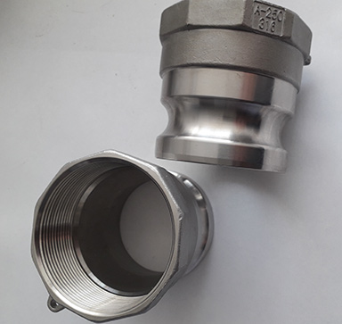
Female adapter type B male BSP thread
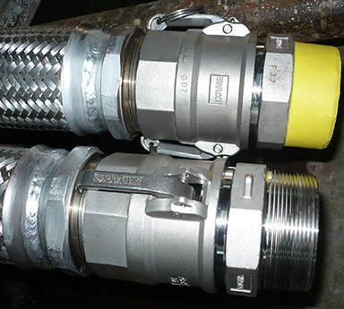
Female adapter with ends type C
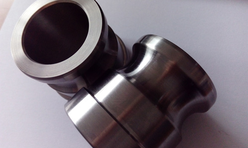
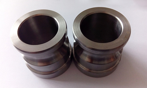
Female adapter type D with female thread BSP
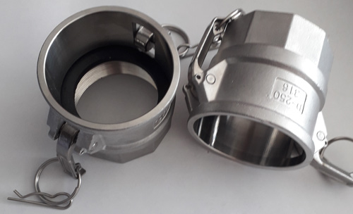
Male adapter type F with male thread BSP
| TYPE FITTINGS |
CONNECTION MATERIAL |
MAX.PERM.OPERATING TEMPERATURE |
|---|---|---|
| MAUN | Stainless steel AISI 316L | 600° C |
| NP (bar) | 16 | 14 | 7 | ||||||
|---|---|---|---|---|---|---|---|---|---|
| DN | 12 | 20 | 25 | 32 | 38 | 50 | 65 | 80 | 100 |
| d | G 1/2" | G 3/4" | G 1" | G 1 1/4" | G 1 1/2" | G 2" | G 2 1/2" | G 3" | G 4" |
Female adapter type B male BSP thread
| TYPE FITTINGS |
CONNECTION MATERIAL |
MAX.PERM.OPERATING TEMPERATURE |
|---|---|---|
| ZSSNB | Stainless steel AISI 316L | 600° C |
| NP (bar) | 16 | 14 | 7 | ||||||
|---|---|---|---|---|---|---|---|---|---|
| DN | 12 | 20 | 25 | 32 | 38 | 50 | 65 | 80 | 100 |
| d | Rp 1/2" | Rp 3/4" | Rp 1" | Rp 1 1/4" | Rp 1 1/2" | Rp 2" | Rp 2 1/2" | Rp 3" | Rp 4" |
Female adapter with ends type C
| TYPE FITTINGS |
CONNECTION MATERIAL |
MAX.PERM.OPERATING TEMPERATURE |
|---|---|---|
| ZSNC | Stainless steel AISI 316L | 600° C |
| NP (bar) | 16 | 14 | 7 | ||||||
|---|---|---|---|---|---|---|---|---|---|
| DN | 12 | 20 | 25 | 32 | 38 | 50 | 65 | 80 | 100 |
Female adapter type D with female thread BSP
| TYPE FITTINGS |
CONNECTION MATERIAL |
MAX.PERM.OPERATING TEMPERATURE |
|---|---|---|
| ZSUND | Stainless steel AISI 316L | 600° C |
| NP (bar) | 16 | 14 | 7 | ||||||
|---|---|---|---|---|---|---|---|---|---|
| DN | 12 | 20 | 25 | 32 | 38 | 50 | 65 | 80 | 100 |
| d | G 1/2" | G 3/4" | G 1" | G 1 1/4" | G 1 1/2" | G 2" | G 2 1/2" | G 3" | G 4" |
Male adapter type F with male thread BSP
| TYPE FITTINGS |
CONNECTION MATERIAL |
MAX.PERM.OPERATING TEMPERATURE |
|---|---|---|
| MASNF | Stainless steel AISI 316L | 600° C |
| NP (bar) | 16 | 14 | 7 | ||||||
|---|---|---|---|---|---|---|---|---|---|
| DN | 12 | 20 | 25 | 32 | 38 | 50 | 65 | 80 | 100 |
| d | Rp 1/2" | Rp 3/4" | Rp 1" | Rp 1 1/4" | Rp 1 1/2" | Rp 2" | Rp 2 1/2" | Rp 3" | Rp 4" |
SMS 63, Ball fitting, pipe fittings with special designs,.....